■Iwatec Renewable Hydrogen Demonstration Plant Progress Vol.03(Piping and hydrogen gas facility installation)

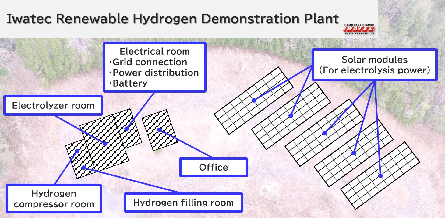
Image1:Facility Layout
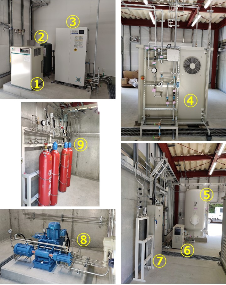
Installation of the plumbing and hydrogen gas system has been completed.

Image2:Installation of piping and hydrogen gas facilities completed
| Equipment | Function | |
| ① | Air Compressor | Generates compressed air for pneumatic equipment control. |
| ② | Air Tank | Stores air generated by air compressor. |
| ③ | Electrolyzer Chiller | Supplies cooling water for Electrolyzer. |
| ④ | Back side of the Electrolyzer with inlet/outlet connections | Electrolyzer feedstock water, as well as coolant and compressed air, are supplied from here. The generated H2 is also fed out of one of these ports to the H2 Buffer Tank. |
| ⑤ | H2 Buffer Tank | Temporarily stores the generated H2 gas before compression. |
| ⑥ | H2 Compressor Chiller | Supplied cooling water for H2 compressor. |
| ⑦ | N2 Supply | Supplies N2 gas for occasional purging of H2 lines |
| ⑧ | H2 compressor | Compresses H2 gas generated at the Electrolyzer into high pressure gas. |
| ⑨ | 2 Filling Line/Filling Equipment | Fills H2 cylinders at a set pressure for storage/transportation. |
Stay tuned for our next update!!
Check out our Hydrogen & Fuel Cell page to learn more about H2, Fuel Cells and our capabilities, by clicking on the ling below.
Get in touch with us.


